
This is based on Big Clive's DMX Tester: http://www.bigclive.com/dmxtest.htm .
This widget helps you find the most common faults in DMX-512 wiring, my added cable finder will help you sort through tons of confusing XLR cables while searching for the one that you want to plug into your DMX controller or audio mixing deck.
DMX-512 is a protocol used on theater stages, film sets and big art festivals to control artistic lighting. If you are yawning "I knew this, dude" right now, this little widget may be useful for you. If you are absolutely puzzled, you will probably not need it.
DMX-512 is a digital serial protocol based on RS-485. Meaning data is transmitted using a differential pair - this minimizes interference.
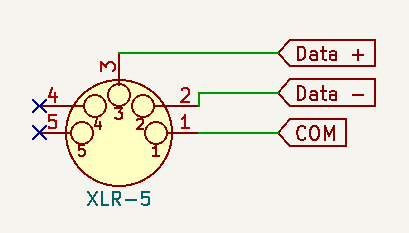
The DMX standard proscribes the XLR-5 plug (see figure 1). Pin 1 is the common ground, pins 2 and 3 are connected to the differential pair. Pins 4 and 5 are reserved for a secondary pair, but in practice they are never used.
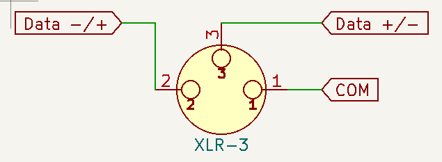
In the real world many of the more affordable light fixtures will use XLR-3 plugs, even though those are explicitly forbidden by the standard (to avoid confusion with audio cables). The pin assignment is usually identical to the XLR-5 plug, but sometimes the two data pins are swapped (which does not matter for the tester).
The differential pair will alternate between 0V and about +5V(1) in reference to the common ground - with the two wires always having opposite voltage. A logical 1 is 5V on Data+ and 0V on Data-, while a logical 0 is 0V on Data+ and 5V on Data-.
(1) on very long cables the voltage can fall to relatively low levels. Under some circumstances it can rise to +7V, bad reflections can create momentary surges to +/-12V.
The high level data protocol is based on the UART protocol. DMX transmits multiple repeats of the light settings every second. Each repeat consists of 25 to 513 bytes representing lighting channels. Each byte also contains start (same as logical 0) and stop (same as logical 1) bits - this means the pair is guaranteed to switch voltage levels multiple times a second as long as the controller is transmitting.
Yes, the above is an extremely simplified description of DMX. If you are interested you can download the detailed standards at ESTA.
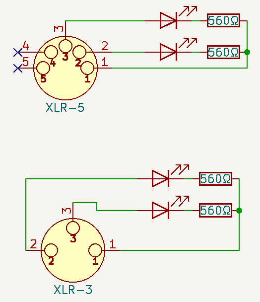
The idea of the tester widget is to connect a LED between common ground and each of the data wires. Whenever a data wire switches to 5V the connected LED will light up. As long as a DMX controller is connected to the DMX cable both data wires are guaranteed to regularly switch polarity.
The resistor should be around 600Ω ±100Ω - the light output of the LEDs will still be high enough to easily see them, but the resistance is high enough to limit the current enough even in surge situations. Simple 0.25W resistors are enough for this application - this is the usual type that you get when ordering cheap THT resistors. There are rare 0.1W resistors, which will heat up quite a bit under some circumstances and should be avoided.
The effect of this arrangement is that both LEDs constantly flicker as the pair switches polarity. It then becomes relatively easy to spot the usual problems:
| LEDs | Diagnosis |
| both flicker | the cable is electrically okay, it may still be un-terminated or have the wrong impedance (i.e. microphone cable) |
| one flickers, one off | one of the data wires is broken, exchange the cable |
| both off | cable not connected, ground wire broken, or both data wires broken; connect the cable or exchange it if already connected |
| both steady on, no flicker | the XLR-3 DMX tester is connected to an audio cable with phantom power or to the cable tester described below |
For most situations you will want to create a XLR-3 and a XLR-5 tester for yourself, so you can use it with any kind of cable/fixture that you come across.
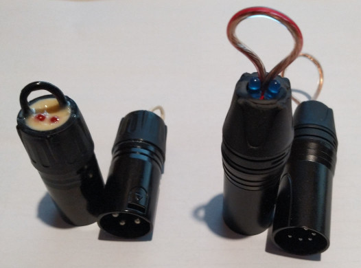
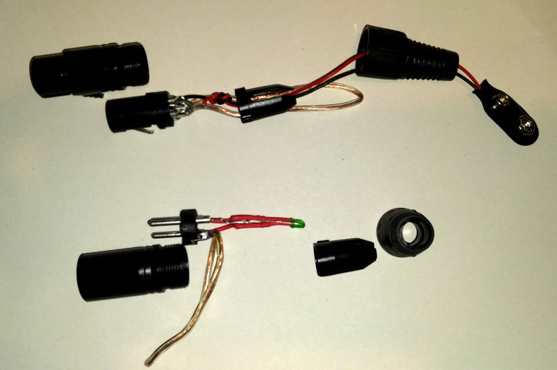
Simply get a male XLR-3 or XLR-5 plug - it can be a cheap one off the likes of Amazon, eBay or Ali-Express. In my experience it is best to shorten the back side a bit to make it easier to fit the LEDs through - the existing cable constraint will hold the LEDs in place nicely. Alternatively remove the cable constraint and fill the plug with epoxy once it is completed. Both is shown in figure 4 (the 3pin XLR left is potted with epoxy, the 5pin XLR on the right is simply held in place by internal mechanical pressure).
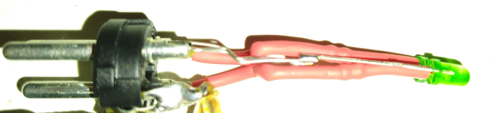
The order of the components does not matter - you can solder the LED to the common (pin 1) and the resistors to the data pins (pins 2/3) or vice versa. Importantly the cathode (negative) of the LED must point towards the common ground and the anode (positive) must point towards the data pin. You should make sure that the leads connected to the two data pins are isolated from each other and the common ground pin. A few pieces of shrink tube will usually do the trick nicely even if the wires have to be bent to stuff them into the plug. You should also make sure the leads are long enough to stick out of the back of the plug (too long is usually not a problem: the leads can be bent). Figure 5 shows how it should look after soldering all components - the resistors are hidden underneath the red shrink tube.
LED notes: 3mm LEDs are easier to fit through the XLR plug. The cathode (negative) is usually the shorter lead and it usually also has a slight flat at that side. However, it is best to test each LED in a common "LED tester" widget to make sure it works.
Side note: the "shield" tab of XLR connectors is usually not connected when using DMX. For my cable testers I simply soldered a soft wire loop to this tab that then allows me to attach the DMX tester widget to a key chain.
Materials per tester widget:
Note: it is possible that your DMX fixtures will misbehave or flicker while the DMX tester is connected, since the RS-485 bus underlying DMX is simply not expecting an LED load and it may create some strong signal reflections on the bus. But then again - you will connect it to a DMX bus that is already behaving in a strange way to diagnose it - the DMX tester may make it slightly worse, but not qualitatively different.
If your DMX tester tells you the cable is okay, but fixtures are still flickering or misbehaving even after removing the tester: make sure the cable is terminated properly and if that does not help - check that you didn't accidentally use a microphone cable instead of a DMX cable.
There are two types of XLR-3 connected microphones in the professional theater world: simple unpowered microphones and those that require phantom power in order to work. There are good resources online to explain the difference and background.
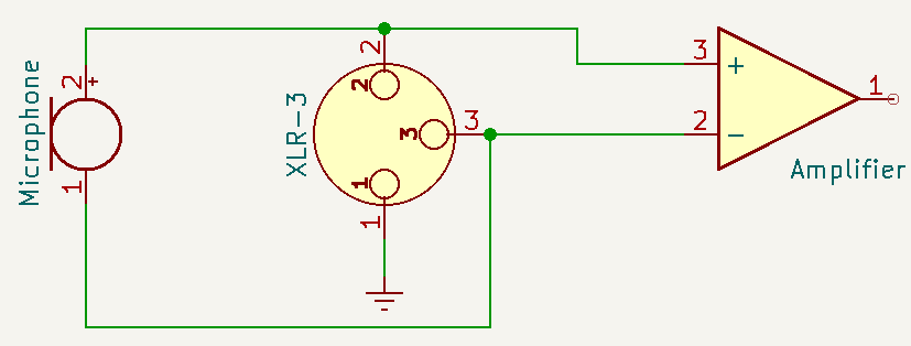
Simple unpowered microphones that use XLR-3 transmit their signal between pins 2 and 3. The audio pre-amplifier then amplifies the differential voltage between those pins to gain a usable signal. Pin 1 is either unconnected or connected to the chassis of the microphone to provide earthing and prevent the artist from getting shocked randomly. The voltage between earth and pins 2+3 is undefined and can float anywhere. See figure 6 on the left.
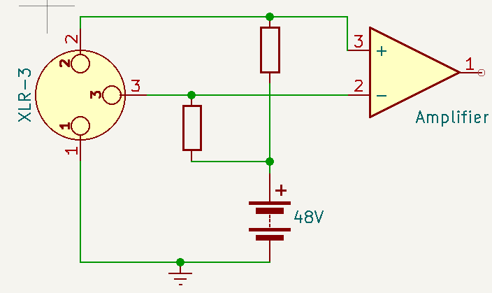
With phantom power a limited current (at 48V) is provided by tying the ground wire on pin 1 to the power supply's ground and adding some resistors between pins 2/3 and the positive pole of the supply. Those resistors are calculated to provide a maximum of 10mA and must be within 1% of each other so that no accidental differential voltage is introduced between pins 2 and 3 - the latter would negatively affect the microphone. On the microphone side another pair of resistors then funnels this current to the electronics that power the microphone.
The idea behind the cable finder is to provide some very limited power into the starting end of a cable so that it can be easily found by connecting the DMX tester to the finishing end. For example with stage box in the dark (just so that labels are hard to read) or a big mess of cables across the lawn of a festival you simply connect the DMX tester to one side and the cable finder to the other side - if the DMX tester lights up both are connected to the same cable, if not you continue connecting one of it to other cables/sockets until it lights up.
If the cables being tested this way are simple DMX cables then this is trivial - simply provide some voltage between pin 1 and either pin 2 or 3. However, there is a chance that an expensive microphone is connected to one end of the cable, so we have to accommodate this eventuality. This is easily done by making sure both pin 2 and 3 are connected to the same (positive) voltage with limited current and two resistors that are very close to each other in value.
A very convenient power supply is a simple 9V block battery. But you need to get a couple of 1kΩ resistors with 1% tolerance - those are very cheap to get, but care should be taken that they really are the 1% type - just in case you should measure them and make sure their values are within 10Ω (1%) of each other. This will usually be the case if they are from the same lot (same order). The value 1kΩ guarantees that the current is limited to 9mA, which is very close to the one expected by powered microphones. With these precautions microphones will (hopefully) not be damaged(2), even if they are accidentally powered by this cable finder. With the 1kΩ resistor on the power supply side and the ~600Ω resistor on the DMX tester side the LEDs will be easily visible.
(2) while not being damaged, the microphone will probably also not function, since 9V is not enough voltage - microphones expect 48V. The 9V are also within the allowed spec for RS-485 receiver circuits, so DMX equipment will not be damaged.
9V battery tabs are quite cheap on the usual platforms and convenient to solder in. Solder the negative (usually black) wire of the battery tab to pin 1 then solder one 1kΩ resistor each into pins 2 and 3. Connect the other end of the resistors to the positive (red) wire of the battery tab and make sure everything is sufficiently isolated using shrink tube. Make a knot into the battery wires, add a zip tie or something similar to make sure it cannot be easily ripped out of the plug.
Each cable tester is complemented by a DMX tester with the same amount of pins.
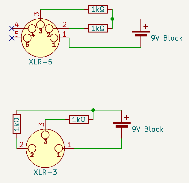
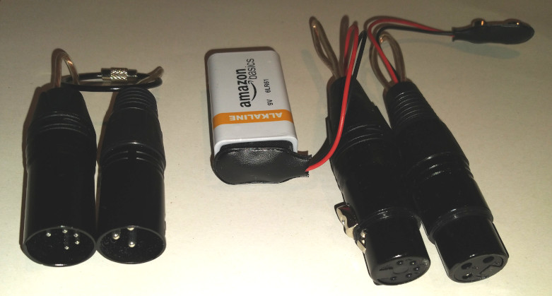
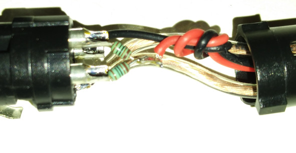
Figure 8 shows the basic schematic for the cable finder. Figure 9 shows a complete set, including the two corresponding DMX testers that are used to find the other end of the cable. Figure 10 shows the inside of a soldered cable finder.
Materials per cable finder:
Note on resistors: the two resistors within each cable finder plug must be within 1% of each other to avoid dangerously different voltage levels on the two pins. It is okay if they have a greater than 1% deviation from 1kΩ. If you only have 5% resistors available this is usually not a big problem: simply measure them and chose a set that is close enough to each other - within the same lot they tend to be relatively close anyway.
Disclaimer: I'm not an Electrical Engineer and my experience with DMX and audio equipment is limited to what I get to see as a hobbyist technician at a small theater stage during my spare time. If you have any doubt about the above circuits - ask a professional! I cannot guarantee anything.